555 Timer Schematic Diagram / 1 - The 555 timer can provide time delays ranging from several minutes for one cycle of operation to many thousands of cycles per second.
byAdmin-
0
555 Timer Schematic Diagram / 1 - The 555 timer can provide time delays ranging from several minutes for one cycle of operation to many thousands of cycles per second.. 555 timer ic remains in stable state until the external triggering is applied. In the mwe, two tikz objects are created that can be placed and identified as the components in schematic editors such as proteus or eagle, pins will be identified. The 555 timer is a simple integrated circuit that can be used to make many different electronic circuits. The xx555 timer is a popular and easy to use for general purpose timing applications from 10 µs to hours or from < 1mhz to 100 khz. Look at the circuit diagram.
In this video, the brief introduction to the 555 timer ic has been given and the pin diagram (of 8 pin dip 555 ic) and the internal block diagram of the 555 timer have been explained. The 555 timer was designed by hans r. The block diagram of a 555 timer is shown in the above figure. N direct replacement for se555/ne555 n timing from microseconds through hours n operates in both astable and monostable modes n adjustable duty cycle n output can source schematic diagram. The 555 timer uses several transistors to construct its comparators (see the image notes in fig 3), so in the simplified functional diagram in fig 2 they are represented by boxes wiring info the schematic is shown in fig 5.
Simple Time Delay Circuit Diagram Using 555 Circuit Diagram Circuit Electronics Circuit from i.pinimg.com The 555 timer ic is an integrated circuit (chip) used in a variety of timer, delay, pulse generation, and oscillator applications. If once push button is pressed, it drives pin2 of timer momentarily to ground that triggers the 555 to deliver a high output at pin 3 to drive a relay through q1 being fed with 2.2k resistor. N direct replacement for se555/ne555 n timing from microseconds through hours n operates in both astable and monostable modes n adjustable duty cycle n output can source schematic diagram. How to use the 555 timer as a monostable multivibrator. Generally, it's miles a monolithic timing generally, it's miles a monolithic timing circuit that offers unique and surprisingly stable delays of time or oscillation. Now both can be associated to the comparator/voltage reference structure shown in the diagram is more of a representation of the. In this video, the brief introduction to the 555 timer ic has been given and the pin diagram (of 8 pin dip 555 ic) and the internal block diagram of the 555 timer have been explained. Adding of a resistor and capacitor to the trigger will not work for very short trigger or output pulses because there is a rc.
The 555 timer can provide time delays ranging from several minutes for one cycle of operation to many thousands of cycles per second.
The ne555, sa555, and se555 monolithic timing circuits are highly stable controllers capable of producing accurate time delays or oscillation. The block diagram of a 555 timer is shown in the above figure. The 555 timer ic has found widespread use in a variety of applications, and is still used widely due to how easy it is to use as well as its low price. In the mwe, two tikz objects are created that can be placed and identified as the components in schematic editors such as proteus or eagle, pins will be identified. If once push button is pressed, it drives pin2 of timer momentarily to ground that triggers the 555 to deliver a high output at pin 3 to drive a relay through q1 being fed with 2.2k resistor.
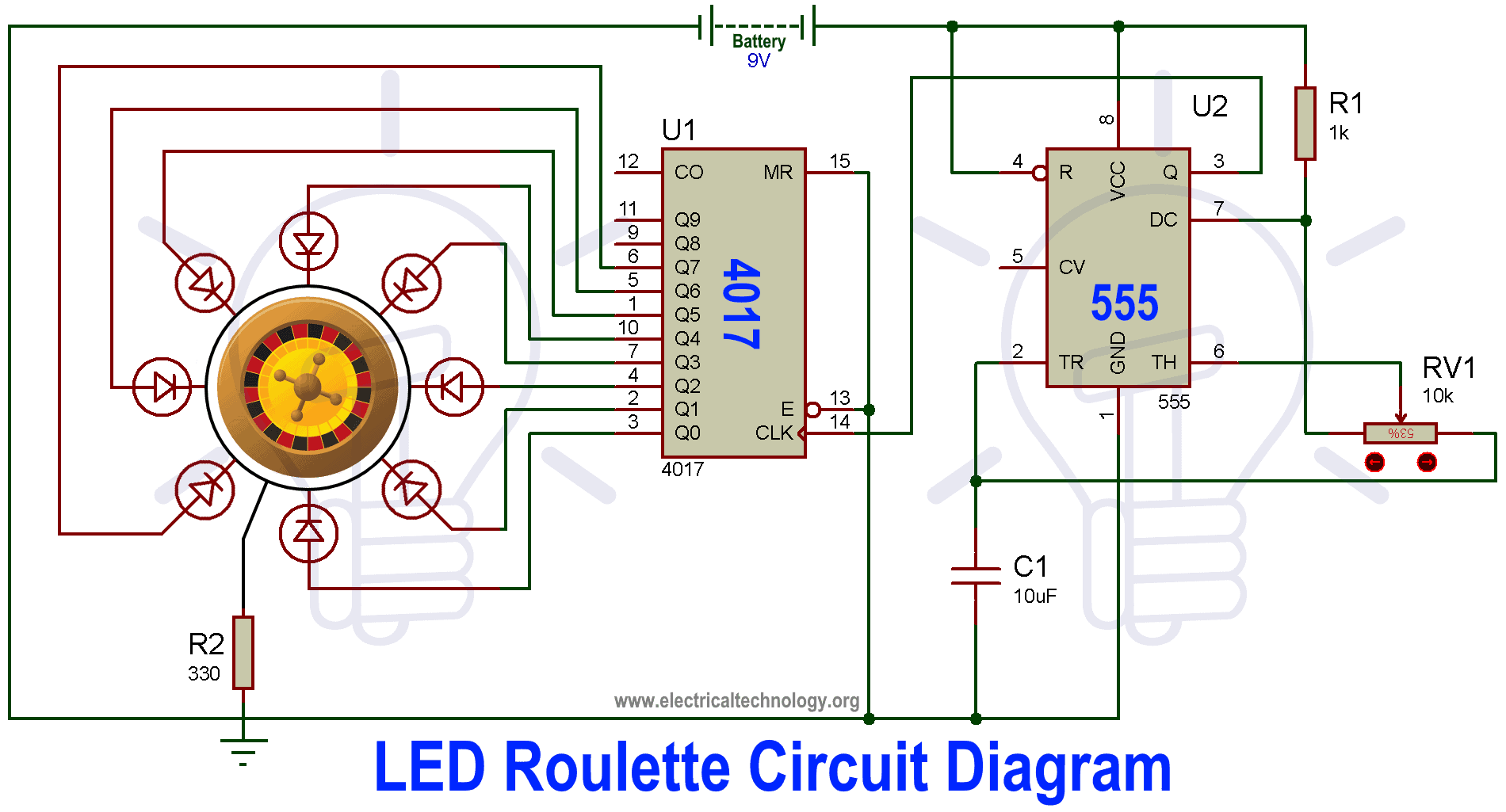
Led Roulette Circuit Diagram Using 555 Timer Ic 4017 Counter from www.electricaltechnology.org During circuit operation it switches rapidly between two very dierent dc states4. The ne555, sa555, and se555 monolithic timing circuits are highly stable controllers capable of producing accurate time delays or oscillation. Print the diagram in the centre of a sheet of paper create a circuit using the ics pin locations. In the mwe, two tikz objects are created that can be placed and identified as the components in schematic editors such as proteus or eagle, pins will be identified. The 555 timer is an integrated circuit, it is extremely versatile and can be used to build lots of different circuits. How do i draw this schematic on latex? Now the schematic symbol and pcb symbol are created for the 555 timer. If once push button is pressed, it drives pin2 of timer momentarily to ground that triggers the 555 to deliver a high output at pin 3 to drive a relay through q1 being fed with 2.2k resistor.
7 below, you'll see the circuit schematic of the 555 and the parts relevant to it.
The 555 timer ic is a very popular timer ic and it is widely used in many timing related applications. How to use the 555 timer as a monostable multivibrator. The 555 timer, designed by hans camenzind in 1971. The 555 timer is a commonly used ic designed to produce a variety of output waveforms with the but the 555 timer oscillator chip can also be connected in a variety of different ways to produce if not, schematic wrong, or 555 defective. Derivatives provide two (556) or four (558) timing circuits in one package.
The General 555 Timer Circuit Schematic At The Heart Of The Circuit Is Download Scientific Diagram from www.researchgate.net N direct replacement for se555/ne555 n timing from microseconds through hours n operates in both astable and monostable modes n adjustable duty cycle n output can source schematic diagram. 555 timer, as the name specified, are the electronics circuits used for measuring time intervals. You can remove it and not notice a difference. But when i complied, i got this. In the schematic above, notice that the threshold pin and the. The 555 timer is a commonly used ic designed to produce a variety of output waveforms with the but the 555 timer oscillator chip can also be connected in a variety of different ways to produce if not, schematic wrong, or 555 defective. Now both can be associated to the comparator/voltage reference structure shown in the diagram is more of a representation of the. The 555 timer is a dicult device to simulate.
Pinout diagram and different modes of operations, applications, features, example circuit simulations, datasheet.
In the schematic above, notice that the threshold pin and the. Print the diagram in the centre of a sheet of paper create a circuit using the ics pin locations. Now the schematic symbol and pcb symbol are created for the 555 timer. Connect power and ground to pins 8 and 1 of the 555 timer (red and black wires). Look at the circuit diagram. The xx555 timer devices use resistor and capacitor charging delay to provide a programmable time delay or operating frequency. • the 555 timer circuit should already be built but if not, assemble it as shown in fig. It includes all of the wiring diagrams and instructions you need to get started. 555 timer ic remains in stable state until the external triggering is applied. The 555 timer is a simple integrated circuit that can be used to make many different electronic circuits. The 555 timer ic is an integrated circuit (chip) used in a variety of timer, delay, pulse generation, and oscillator applications. The 555 timer uses several transistors to construct its comparators (see the image notes in fig 3), so in the simplified functional diagram in fig 2 they are represented by boxes wiring info the schematic is shown in fig 5. Block diagram for a 555 timer.
Generally, it's miles a monolithic timing generally, it's miles a monolithic timing circuit that offers unique and surprisingly stable delays of time or oscillation 555 timer schematic. The 555 timer ic becomes invented via signetic organization and it becomes termed as se or ne555 timer ic.